This diagnostic article takes you through the process our AECS technical support team use with problematic vehicles. We look at the issues involved and share how we resolved the problem. This an inside look, from the profound to everyday issues automotive workshops encounter.
Problem presented from the workshop to our technical support team
A Mazda had arrived for repair with automatic transmission issues. We can select reverse and drive – in which it only seems to select third gear. Our Launch Eurotab scanner cannot communicate with the Transmission control unit.
Also, in the engine (PCM) and ABS both have fault codes that they also cannot communicate with the TCM.
I can see on the ATS 4 channel differential/offset scope that the TCM appears to be talking to the CAN bus, but that no one seems to be able to understand the TCM. We have checked power and grounds on the TCM and all seem to be properly present.
Have you got any thoughts?
Measure
Well please let’s first see the scope recordings you have made.
First CAN data bus recording recorded as close to the TCM as possible.
In the CAN data analyser I have circled the areas of first concern, the Ack (A) and the DLC (B). Both look perfect, when scrolling through the table, there are no non-Ack messages, nor does the DLC count give incorrect numbers. The voltages of the actual CAN signals appear fine to me too.
Time pressure
The next thing is where time pressure comes into play. We (at AECS Technical Support) did not take enough time to explain what to do next, as we do during our four-hour CAN data bus training. We simply cannot do a quick four-hour training during a tech support phone call.
Resistor
We explain in the CAN data training that to determine if an ECU actually speaks on the bus, you need to fit a resistor in, for example, the CAN high and measure the signal on both sides of the resistor.
The diagnostician fitted a 120 Ohm resistor in the CAN high wire, this was wrong. The 120 Ohm resistor is the value of the capping resistor and should not be used for the intended diagnostic purpose.
It looks like two stories were mixed. This did not produce the result I wanted.
Zoomed in recording made on both sides of the resistor.
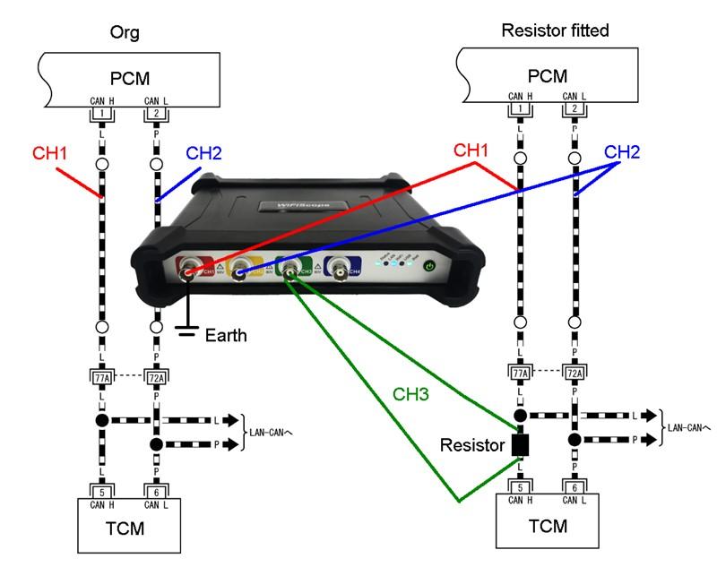
We asked the diagnostician to use Channel 1 and 2 as an offset scope with one combined earth, and to use Channel 3 as a differential scope. The ATS WiFi Scope allows you to choose freely if you want to measure from earth or if you want to measure across a component (the resistor) without the chance of creating a damaging earth loop (or short the CANbus).
You can connect each channel’s earth leads to the same ground or you can combine the earths so that only one connection to battery negative needs to be made, which is less messy and reduces the chance of faulty measurements. Check out the connection diagram and see how we have mixed the connection options.
Also, look at the scope screen detail so you can see how to turn each channel of the scope from offset to differential at will.
Even if a mistake is made and an ‘earth loop’ is created, the earth switches are variable automatic trip switches. This means when a load is detected through the earth circuit larger than an adjustable value (say that the earth lead of CH2 accidentally touches battery positive), the scope switches automatically to a differential function, saving the vehicle’s circuit, the scope and the leads from burning up.
Connection diagram, study how this unique offset/differential ATS WiFi scope is connected. CH1 is offset, CH2 is offset through the earth of CH1, CH3 is differential.
Screenshot.
In the above screen shot you can see at (A) that CH1 and CH2 are switched to be offset scopes, and at (B) that CH3 and CH4 are switched to be differential scopes, even though CH4 is not being used.
Please note this in the following recordings, makes you a pro spotting (and understanding) detail like that!
There are no other tools on the market that are able to do the special diagnostics the scopes such as the ATS can do.
After fitting the correct resistor and hooking up like above, we got the following recording:
This recording clearly showed on CH3 that no data was sent from the TCM onto the CAN bus.
It pays to hoard…
The diagnostician at the workshop happened to have a known bad TCM from a similar vehicle ‘laying around’, I mean who wouldn’t? Although the spare TCM was known to be faulty, it was also known to be able to be communicated with when removed from its original vehicle.
When checking the timing of the pattern on CH3 (circled) we found in the CAN analyser table that, for example, the IDs 131, 150, 160, and 228 are sent by the TCM. We could not find those IDs in the analyser of the previous ‘bad’ recording.
Recording made with communicating TCM fitted in the problem vehicle.
Zoom-Zoom
The second hand TCM ECU did speak on the CAN bus as seen in the differential measurement on CH3 (circled). This concluded immediately that the power supplies and earths of the TCM where fine, as the second hand TCM was plugged in the wiring harness of the vehicle.
Conclusion
A new TCM was ordered and fitted, the car is running and shifting as it should now, with no further codes in the system. How nice and quick diagnostics can be!
Jobs like this command premium dollars. Granted, this is not work for the ‘oil changer’ type of technician. This is for the better level of technicians in NZ (diagnosticians), and we see most of them on a regular basis in our training seminars throughout New Zealand.
The level of equipment and the level of training used in this job are within easy reach for everyone who’s keen to stay in control of their career in automotive. We are simply here to make it easy with our technical support.
Be effective and profitable, call us to make the next easy move.


