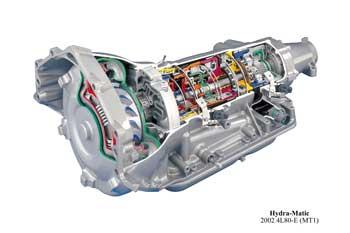
| The basic purpose of an automatic transmission is to provide a forward and reverse driving range that increases the torque between the engine and the drive wheels. Rather than having a solid conventional clutch as in a manual transmission, automatic transmissions utilize a fluid coupling device called a torque converter to transmit power from the engine to the transmission. Hydraulic pressure in the converter allows power flow from the torque converter to the transmission’s input shaft. The only time a torque converter is mechanically connected to the transmission is during torque converter lockup, generally at relatively high speeds (highway speeds) and no load. The input shaft of the automatic transmission drives a planetary gearset which provides different forward gears, a neutral position, and reverse. Power flow through the gears is controlled by multiple-disc clutches, one way valves and friction bands. These friction elements either hold or turn the gear sets to provide different gear ratios. The control valve assembly (valve body) controls the hydraulic pressure required to operate the clutches and bands that shift the gears automatically. By holding different parts of the planetary gearset, different gear ratios are obtained. When the gear selector is moved to a given forward driving range, the “drive” position for example, the transmission shifts itself up or down depending on vehicle speed, throttle position and engine load. Electronically controlled automatic transmissions were first introduced in the mid-1980s, with electronics used to control the timing and length of shifts, as well as to engage and release the clutches. Newer advances in automatic transmissions include continuously variable transmissions (CVT), which do not use specific gear ratios, rather an infinite number of ratios based on a belt moving on a variable diameter spool. Continuously slipping torque converters are also gaining popularity as they improve fuel economy. As automatic transmissions employ a fluid coupling between the engine and transmission, they have always been at a fuel economy disadvantage to manual transmissions, which employ a solid clutch coupling. Planetary Gear System Automatic transmissions use a gear system that does not require gear shifts to change gear ratios. A simple planetary gearset is made up of three elements, the sun gear, the planet carrier assembly and the internal ring gear. The sun gear is so called because it is at the center of the gearset. The other gears revolve around it like planets around the sun. The planet carrier assembly holds the planet pinions within a cage, or carrier. The pinions rotate on pins and are meshed with the sun gear at all times. The internal ring gear has its teeth cut on the inside of the gear, and these teeth are constantly in mesh with the pinions. This planetary system rotates on the same axis, with input and output power on this same axis, so that the gears are never disengaged to change ratios. By causing one of the planetary gearset members to be stationary, and the other two still turning, a different output ratio is obtained. The holding of one member is done by a band or clutch pack using hydraulic pressure routed by the valve body. Each gearset member is attached to an input or output shaft in order to transfer power when the gear ratio is changed. Holding Devices There are two elements used to hold members of the planetary gearset, so another member can provide the output drive. These devices are transmission bands and multiple-disc clutches, also called clutch packs. Transmission bands tighten around the outside of a drum and keep the drum from turning. The drum is engaged with a member of the gearset, so if the drum does not turn, that member of the gearset does not turn. The band is anchored at one end and mechanical action against the other end is activated by hydraulic pressure via the valve body, which tightens the band. Multiple-disc clutches hold one or more members of the planetary gearset, via a hydraulically activated piston that locks the clutches together when hydraulic pressure is applied to the piston. The inside diameter of the clutch pack is splined to an input or output shaft. Multiple-disc clutches are used more than any other type of holding device in an automatic transmission. There may be as many as six different clutch packs in an overdrive transmission. Overdrive is a gear ratio in which the output shaft turns faster than the input shaft, which provides very low torque, but very good high speed fuel economy. Torque Converters The torque converter couples and uncouples the engine and the transmission. Converters use impellers and turbines, with vanes, to develop fluid flow and the transfer of torque. In addition to an impeller and turbine, torque converters use a stator to accelerate the flow of fluid from the impeller to the turbine and back to the impeller, thereby multiplying torque. Whenever the impeller moves faster than the turbine, torque is multiplied. A torque converter consists of: • An impeller (pump, or driven member) • The turbine (driven member) • The stator (reaction member) |
The torque converter housing is filled with fluid by the transmission pump. The impeller is the driving member with its curved vanes picking up fluid in the converter housing and directing it toward the turbine. |